
3D Object reconstruction using Depth Sensors
Introduction
This project experiments with scanning real-life objects and generating its 3D model in virtual reality. Using a depth sensor, and circling the object of interest, we can generate a point cloud for a set of angles while the corresponding texture/color map. After some cleaning, the individual point clouds are stitched to create a 3D model. The last step would be to render a mesh over the obtained points. As a constraint, this project may be limited to scanning objects with simple geometrical shapes and using sensors at fixed locations. I did this project as a part of my Computational Geometery course taught by Dr. Renold Bailey.
Background information about the problem
This project works with depth sensors, capturing point clouds and working on them. The general approach to such a problem would be to divide the project into subparts and develop them individually.
-
Acquisition: The capture sensor can either be fixed in position or can be moved around the object. Depending on the scenario, you would either need to understand the pose of the sensor, or the object. Another decision one has to make is the type of sensor. Stereo-vision based cameras would specifically require extrinsics calibration to calculate depth, while a depth sensor typically is pre-calibrated and provides direct access to the depth field. This project works with a fixed position structured light sensor and an object rotating on a turntable.
-
Cleaning: While cleaning as a step can either go into the Acquisition or Processing phase, I decided to keep it separate because of the different methods one can use. This step generally involved removing outliers or fitting points to a plane to help obtain an accurate 3D representation. This project uses a simple Statistical Outlier Removal filter to remove noise in the point cloud.
-
Point cloud processing and alignment: A common approach to align two point clouds is to use the Iterative Closest Points algorithm. The goal is to align the two or more point clouds together and merge them into one. For the project, consecutive point clouds are stitched sequentially to build the 3D object.
-
Surface rendering: This is the final step that would give the object some detail and add realism to it. A common approach is to Delaunay triangulation of some type to generate a mesh of the object. This part of the project is pending.
Inputs to and Outputs from the system
As a whole, the input to the system is an object that will be scanned and the output would be a representative 3D model of it. But considering just the software components, the input is a set of point clouds and the output is a stitched point cloud representing the object scanned.
Needs for the problem domain
With the growth of fields like Augmented reality, Virtual reality, and 3D printing, there is a need to accurately map real-life objects. Two, now common, applications are listed below:
-
Many security solutions are using structured light to perform facial recognition. Such applications use point clouds and meshes to process and build facial features.
-
The boost in 3D printing has led to the development of laser scanners to map objects accurately.
For security-based applications, quick response times would be preferred; Having an algorithm that works with some approximation will work faster than usual. For example, an approximation based algorithm could choose to cut off an iterative algorithm based on the number of iterations instead of the precision required. But for certain applications, accuracy is of utmost importance. An application involving working with generated 3D models for fabrication would prefer to trade time for accuracy.
Related projects
Most related projects, while using depth sensors, deal with reconstructing an entire environment and not a particular object and allow the sensor to be moved freely. Few research topics and applications are listed below:
- BundleFusion: Real-time Globally Consistent 3D Reconstruction
- Structure sensor
- 3D Reconstruction for Featureless Scenes with Curvature Hints
- CowTech Ciclop 3D scanner
- Project Tango
Setup
To perform a 3D reconstruction, I’d require to capture how the object looks from different angles. A turntable was set up, upon which the object will be placed. The depth sensor would be at a fixed position and will be triggered to capture point clouds at specified angles. Let’s have a deeper look into the setup.
Depth Sensor
The depth sensor used is the PrimeSense Carmine 1.09 sensor. This is a short-range sensor and uses structured light to paint the scene. Based on how the light appears distorted, the depth of the object is determined and a point cloud is generated.
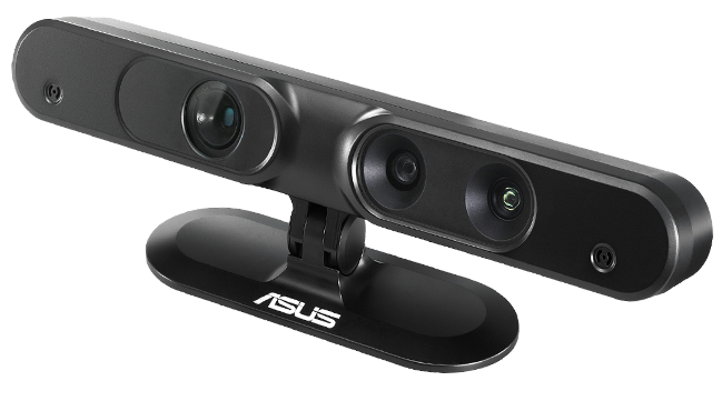 PrimeSense Carmine 1.09 Depth sensor
Turntable
To capture the object from every angle, I placed a turntable on a flat surface with angles marked at intervals of 45 degrees. The object would be placed at the center and rotated around its vertical axis.
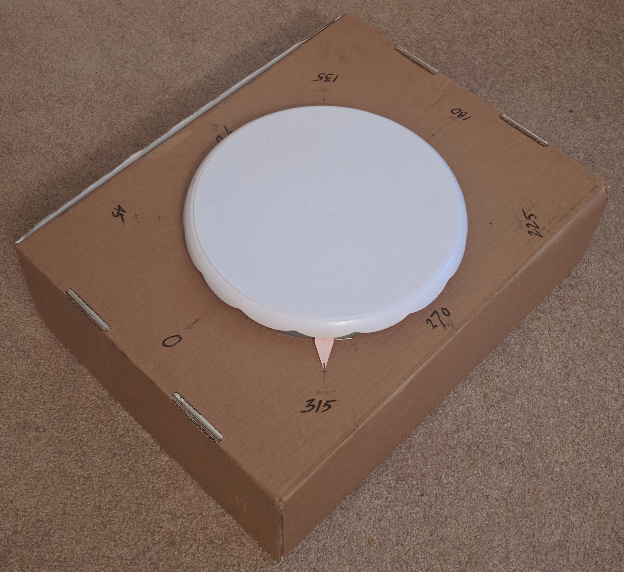 The turntable
Turntable angles
Software
For manual edits, viewing and other functions I used the open-source CloudCompare tool. The Point Cloud Library (PCL) was used in conjunction with the middleware and the Primesense drivers to capture and process the points.
Acquisition
The OpenNI middleware and Primesense drivers help in identifying and communicating with the Primesense sensor. Point cloud data can be directly acquired by setting a particular flag variable while instantiating the camera. The point cloud once acquired, is written to the local disk in the .pcd format that PCL uses. The program was adapted from a few examples on the PCL website.
Cleaning
Any sensor is susceptible to some noise from the environment. While the structured light sensor accurately obtains the depth from the scene, we can observe some noise around the objects. I used the Statistical Outlier Removal method to remove these points. While the result was not ideal, it was better than the initial input.
Image stitched without any cleaning, notice how the point clouds were misaligned
As the sensor could only be tilted upwards in my setup, I had to mount it upside down to the base of the table. This resulted in my cloud points being visualized upside down. An easy fix was to use a negative Y value to flip the axis using setCameraPosition while using the PCLVisualizer.
Stitching
I stitch each captured point cloud sequentially to obtain a 3D reconstruction using the Iterative Closest Points (ICP) algorithm. This process is termed as point cloud Registration. Here is a high-level outline of how the algorithm works:
- Iterate until error/difference is within the threshold limit.
- Identify keypoints and compute its descriptors
- Identify mutual keypoints across point clouds and register them as pairs
- Estimate the transformation to minimize the distance between the points and their corresponding matches
- Perform the transformation and compute the error/difference.
Testing and Results
Here are three objects I used to test the setup – a Rubik’s cube, a box of Ritz crackers, and a model of a house.
-
The cube has a simple geometric structure, different colors, and various corners. All of this would be ideal while the algorithm searches for keypoints. The only challenge would be to reproduce the crevices between blocks. This object would be a great candidate for the stereo vision setup.

-
The box was chosen because of its simple geometric shape along with a rich amount of features in the form of graphics. This should be the easiest to reproduce.

-
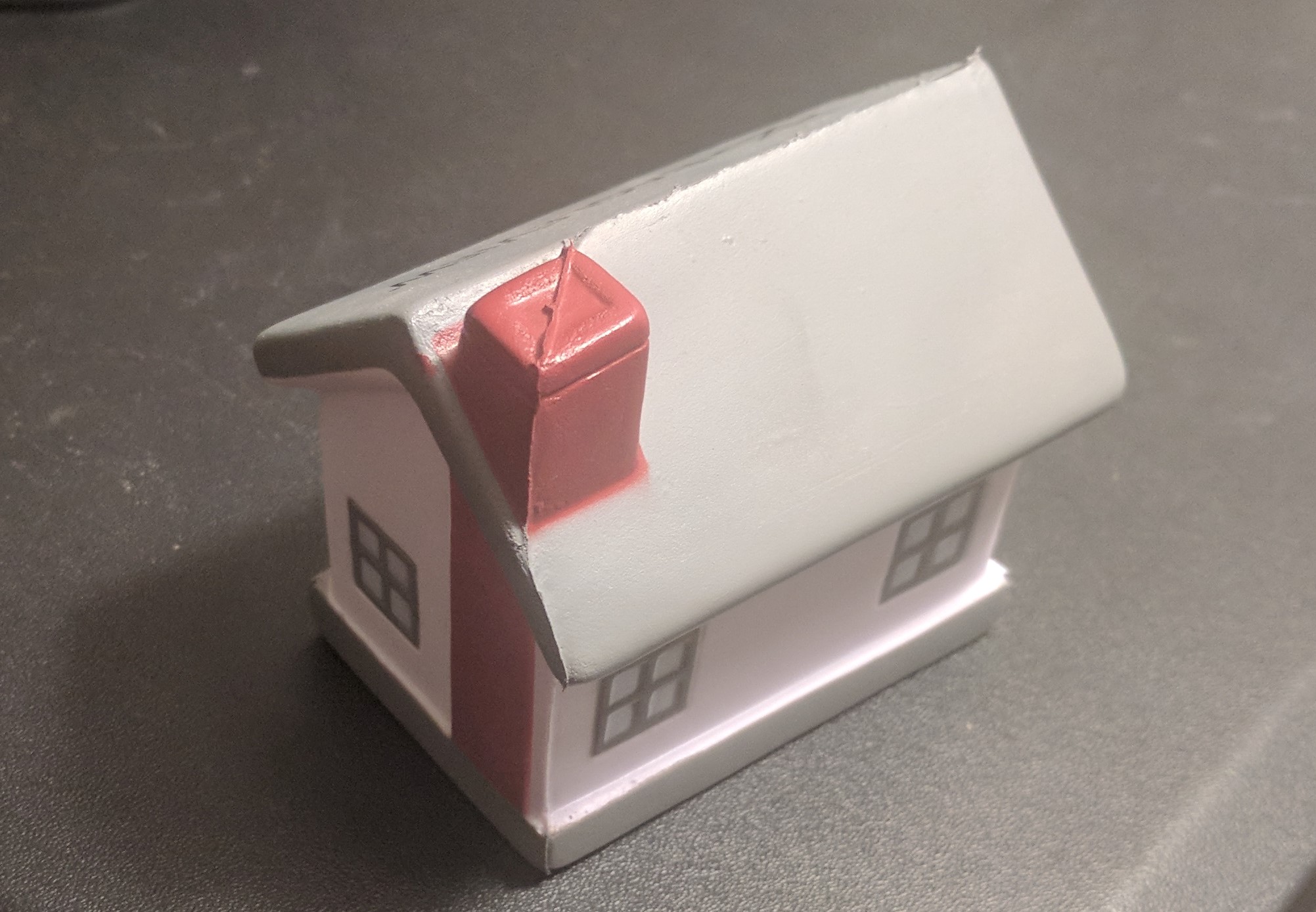
The house was a more complex object. While it did have many corners, the complex geometry might be hard to reproduce.
Rubik’s cube
As you can see, the structure of the Rubik’s cube has been maintained well. There are certain places where outliers are still visible. While the ICP algorithm has been able to stitch the point clouds quite effectively, there are places where there are misalignments. This is because of the approximation from the algorithm. As future work, some sub-sampling can be done for overlapping areas to improve overall quality.
Box
The box has been reproduced the best amongst them all. While there are slight misalignments on the bottom part of the box, most outliers have been removed.
House
This shows how the algorithm fails. The house had many possible keypoints, yet it did fail. This is because of the nature of the ICP algorithm; the algorithm works well when the two-point clouds are coarsely pre-aligned and when the correct keypoints are matched. However, there were some incorrect matches, hence the result.
Stereo Sensor
I also wanted to experiment with point clouds generated by a stereo setup. Getting point clouds using a structured light sensor is pretty straightforward; Using PCL to obtain the point cloud directly. But with stereo camera sensors, the camera rig must first undergo stereo calibration i.e. understanding the relationship between the two cameras in 3D space. The captured images then have to be rectified. Then, using the the baseline of the camera, a disparity map will be calculated which can be inverted to produce depth. I started building a stereo rig for the purpose and used 2 Logitech c270 cameras. I even picked up a dual camera mount and with the help of a few friends from the College of Engineering’s machine shop, got the cameras securely mountedthen have to be rectified cThen, using the the baseline of the , the dual camera which can be inverted to https://raw.githubusercontent.com/srinathos/website-images/master/3DReconstruction/images/stereo_camera_mount.jpg) Stereo cameras mounted on the dual camera mount
The mount easily sits on a tripod and can have a wide variety of adjustments. Unfortunately, I had to reduce scope in order to ship.
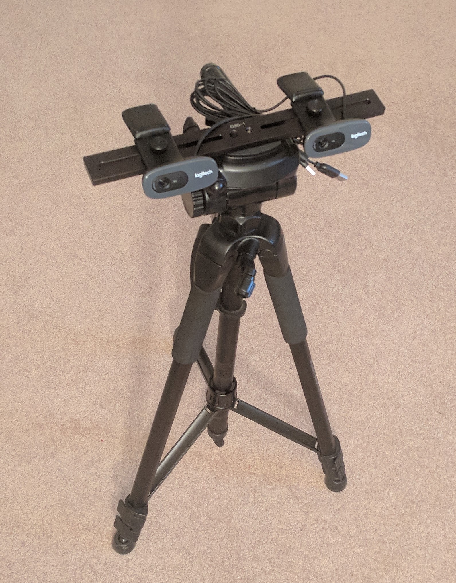 Final Stereo camera setup
Future work
- This particular implementation looks for keypoints on the object and stitches the clouds. A better approach would be to have robust keypoints on the turntable itself and transform/merge the clouds solely on those kepoints. This would avoid issues with smooth objects or objects with a lack of keypoints.
- Stereo vs structured light
- The project captures clouds points from 8 angles. We should get better results and higher fidelity by capturing more angles.
- Experimenting with different outlier removal methods. The radius outlier removal tool looks like a good candidate.